Extruded vectors
This representation extrudes polygons and polylines into boxes and walls, whose height is controllable. They can be used to represent polygons as buildings.
See per-instances properties here: ExtrudedGeometryVectorRepr.
When a polygon is flat (that is when all its clamped points have the same altitude, and its extrusion is 0), it will appear double-sided.
The colour of the facades is interpolated between two colours, from top to bottom. Using a darker colour for the lower part of the geometry can help with both the aesthetics and readability of the scene. The colour of the roof is also independent from both facade colours.
This representation also offers an option for adding bevels to the extruded geometry, however this is subject to some restrictions and increases memory usage. See the protocol documentation for more information.
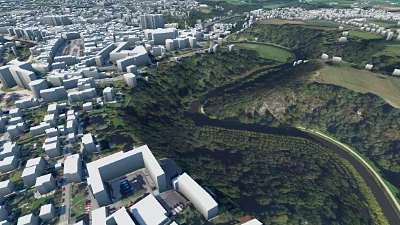
DTM & LOD 1 buildings
Go to gallery demo
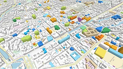
Label palette
Go to gallery demo
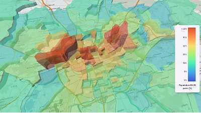
CSV data & histogram
Go to gallery demo
Conforming to the planet’s curvature
Because the planet is round, extruded vector geometries cannot be simple prisms. If they were, large extruded vectors would intersect with the ground. In order to maintain a roughly constant elevation above the planet’s surface, extruded vectors are automatically subdivided into a set of triangles with a rounded overall shape.
However the lower the extrusion height, the smaller these triangles must be in order to be entirely above ground. For very large geometries (which makes them significantly curved) that have a low extrusion height, the required number of triangles would be impractically high. So in these cases a hard limit is applied when the subdivision is computed and the visual representations can be incorrect.
In short, if extruded vectors intersect with the ground, raise the extrusion height. A good thumb rule is that the extrusion height should not be under a thousandth of the tile width.